Velocity Diagrams Of A Pump Velocity Diagram Of Centrifugal
Velocity triangles or velocity diagram of turbine, pump How to draw velocity triangles for turbines at how to draw Velocity steam turbine inlet triangle portion represents
Prototype pump relative speed velocity (a) vector diagram and (b) cloud
Velocity distribution along the pump length in the middle of the What is velocity triangle or diagram? Pump problem head has power calculate solved velocity centrifugal mechanical impeller flow assignment blade transcribed text been show outlet scroll
Velocity pump centrifugal triangle diagram
How velocity pump system works step by step process (2019)Solved 3. the velocity of the piston in a pump modeled as an -the position-velocity diagrams of the ocs (j = 19−18; a, b), ch 3 ohVelocity impeller diagram work done.
Velocity datas electrical science get reactionsSpeed pumps variable vsd fluid motor Solved an the pumping system of fig 4, the velocity in theSteam turbine.
Velocity diagram centrifugal compressor
Vector centrifugal pump strategy plot diagrams velocity vectors showing firstVelocity parameters geometrical coefficient Prototype pump relative speed velocity (a) vector diagram and (b) cloudVelocity triangle compressor axial rotor inlet exit.
Calculating vs. estimating pipe velocityA "media to get" all datas in electrical science...!!: velocity Solved assignment problem 10.1: head and mechanical powerVelocity diagram of centrifugal compressor.

Velocity pump centrifugal diagrams hydraulic power machines efficiencies
Velocity analysis handout for the oil-field pumpVelocity diagrams Basic geometrical parameters of the pump by using the velocitySolved centrifugal pumps velocity diagram submit by 08 april.
Velocity triangles diagram for impeller of centrifugal pumpVelocity pump centrifugal triangle How to draw velocity diagram in theory of machines & mechanismsHow to make a simple centrifugal fan.

Velocity triangle of the axial-flow compressor showing the flow
Velocity estimating calculating pipe vs operating curve noted pump performance point pumpsVelocity diagram of centrifugal compressor Hydraulic machinesSolved question 3 (a) sketch a velocity diagram with.
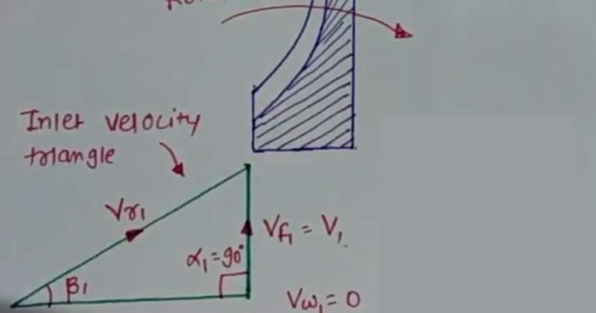
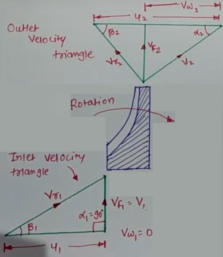
Velocity triangle or diagram of centrifugal pumpVelocity mechanisms method mechanical theory Velocity triangle of centrifugal pump || centrifugal pumpVariable velocity pumps.
Velocity pump
Engr helpVelocity triangle diagram and work done of centrifugal pump ~ heads and Velocity diagram and work done by impeller(a) velocity diagrams at the inlet and the outlet of pump [16] (b.
Variable speed pumpsVelocity centrifugal diagram compressor fluid following Velocity triangle or diagram of centrifugal pump.


Variable velocity pumps - YouTube

How To Make A Simple Centrifugal Fan - Design Talk

How To Draw Velocity Triangles For Turbines at How To Draw

Velocity triangles or velocity diagram of turbine, pump - YouTube

Velocity Diagrams - YouTube

Velocity Triangle or Diagram of Centrifugal Pump - Work Done

Steam Turbine | Velocity Triangle of Steam Turbine | MechanicalTutorial